Atari Classics Vol. 2 No. 6 December 1993
An Idea Is Born
I was pretty impressed with Ben Poehland's "Super Video 2.0" articles in his final months at Current Notes. His in-depth analysis of the problems he found in the 800XL, and his explanations of why he made the changes he did, gave me some insights I never had before. The knowledge he passed on spurred my curiosity and at the same time filled me with the confidence that comes with an in-depth understanding of any problem.
I'm an aficionado of the XE, and I was frustrated that The Alchemist's video upgrade only dealt with the 800XL. In his work he only briefly mentioned how defects in the XE's video output were similar to, and in some ways derived from, the problems Atari designed into the XL series. This only whetted my appetite. I could see the grainy background on my XE display that Ben described, and in addition I had never been happy with the XE's weak color performance which The Alchemist didn't discuss at all. With so much groundwork laid by The Alchemist, I found the urge to apply his ideas and principles to the XE irresistible. The idea that an XL owner should have a machine that produced better video than my XE was, well, a matter of dignity.
 I didn't have any hardware documentation for my XE. This was a problem. You
just can't go tearing into computers without the docs. I've noticed The
Alchemist in his articles seems to draw heavily upon hardware information he's
collected in his travels, he must have a ton of Atari hardware manuals. [Yup
Two tons, actually. Bought, begged, Borrowed, and stolen. And they're mine!
All mine!! Hah! Alchemist] So the first thing to do was get the Sams
ComputerFacts for the 130XE. I purchased it from Best Electronics.
I didn't have any hardware documentation for my XE. This was a problem. You
just can't go tearing into computers without the docs. I've noticed The
Alchemist in his articles seems to draw heavily upon hardware information he's
collected in his travels, he must have a ton of Atari hardware manuals. [Yup
Two tons, actually. Bought, begged, Borrowed, and stolen. And they're mine!
All mine!! Hah! Alchemist] So the first thing to do was get the Sams
ComputerFacts for the 130XE. I purchased it from Best Electronics.
Butchers--Or Bunglers?
With the ComputerFacts diagrams in hand, I opened up my 130XE and started looking at the XE video circuits. I started with the monochrome video amp Q3 first, since Ben had indicated this to be a source of video problems in the XE. The first thing I noticed was that Atari had again used the same incorrect 100-ohm value of output impedance (R53 in Figure 1) as they designed into the XL's. At the same time, they made another change in an apparent attempt to fix it: they lowered the value of the series output resistor from 75 ohms (which was correct in the XL design) to 47 ohms.
It's important to understand that R53 sets the output impedance, while R204 determines the series or "reflected" impedance (the impedance the monitor input "sees" looking back at the computer). This series resistance also protects the transistor by ensuring a load on the output under worst-case conditions, such as a short-circuit across the output. Having set the output impedance 25 ohms too high, Atari "fixed" it by setting the series impedance 28 ohms too low. This is weird, and it doesn't really fix anything: the only thing Atari accomplished here was to mangle the overall impedance of the circuit. In my communications with Ben he occasionally mentioned that Atari didn't understand video signals very well. Now I understood what he meant. If you want independent confirmation that the old Alchemist was onto something, this is it. It also shows that Atari realized there were problems here and made a slapstick effort to homogenize the mess.
Atari also repeated another design error in the XE monochrome amp they had made in the XL: Q3 is "starved" for current because the value of R116 is too high. I made a note of it, but it didn't worry me much. The Alchemist already had shown how to cure that in the 800XL.
 Color by The Keystone Kops
Next I looked at the color circuit in my XE. This was territory not previously explored by Ben, so I was on my own here. Fortunately my task was made easier by the fact that Atari greatly simplified the color output circuits in the XE. Instead of the XL's three transistors, in the XE there's only one: Q2 in Fig. 1. The sole function of this lone transistor is to bring out the chrominance signal to pin 5 of the output jack, and the circuit is fairly simple.
Even so, Atari botched it. Same old problem: output impedance. Having erred on the side of too-low impedance in the monochrome circuit, here they made the impedance way too high, so the color output signal is effectively attenuated. That's why luma-chroma color displays on the XE have that bleached-out look. Resistors R202 and R205 (180 ohms and 150 ohms respectively) need to both be reduced to 75 ohms to achieve a strong color output signal. One can only wonder what was in the minds of Atari's designers when these circuits were laid out. A Hollywood comedy team could have done just as well. Which team might it have been? Laurel and Hardy? Abbott and Costello? The Three Stooges? Or maybe, the Keystone Kops?
At this point I encountered an evil little problem with my Sams diagrams: there's an error in the schematics! If you buy the Sam ComputerFacts for the 130XE, be aware the pinouts on the video jack are incorrectly labeled. Pins 1 and 3 (luminance and audio) are correctly labeled, and pin 2 is shown connected to ground: these are all OK. But pin 5 is shown in the Sams diagrams as Composite Video, when it should be labeled Chrominance. And pin 4, which has no label at all, should be labeled Composite Video. Maybe there's a comedy team at Sams, too? Well, I'm not laughing.
A final comment on the XE video design before we start fixing up things: in the diagrams the RF modulator is shown as a "black box", with no indication of what's inside. Yet, the RF modulator in the XE plays a more significant role than the one in the XL machines. Not only does it provide the RF output to the antenna terminals for a TV interface, but it also contains the channel selector switch and outputs the composite video signal to pin 4 of the videojack. That's a lot of functions assigned to one "mystery component". If it fails, you lose two of your video interfaces at once (composite video and TV). What happens if it does fail - can you fix it? Not likely! If you pry off the top of this little box and look inside, you'll see why. There isn't much to see. The innards consist of a little circuit board crammed with micro miniature surface-mount components. If it fails, desolder the whole box and throw it away, then buy a new one from Best. You can't even see these things, much less repair them.
Super Video XE Mods
(Note: I have made modifications to the following. The original article paralleled two resistors to achieve a given resistance. I just have you remove one resistor and replace it with another. You can get a very nice solder sucker and some solder wick at Radio Shack. If you plan on doing any of these type of modifications at all, these are a must have.)
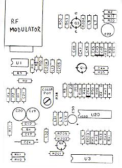
Parts for this upgrade are simpler than for the corresponding upgrades on the XL machines. You'll need a 10uf/16v tantalum capacitor, a 100uf/16v or 220uF/16V radial electrolytic capacitor (the larger value is preferred if it's the same physical size as the 100uf unit), and some common 1/4-resistors, all readily available at Radio Shack (Note: if you can't find a 8.2-ohm resistor to replace R116 with, use a 10-ohm instead). If you purchased the bag of resistors at Radio Shack recommended by The Alchemist in his "Super Video 2.1XL" article you'll be in great shape. Refer to the schematic of Fig. 2 and the board diagram of Fig. 3 as you perform the following steps.
Step 1. Locate R116, a 51-ohm resistor (green-brown-black-gold) on the 130XE motherboard (it's fourth in the line of components to the right of the color tuning pot). Remove this resistor from the board and replace it with a 8.2 ohm resistor (gray-red-gold-gold).
Step 2. Locate the video output transistor Q3; the flat side faces left, and the lead connections are at the top, left side, and bottom. The bottom lead is the collector. Select a 10uf tantalum capacitor and trim its leads to an appropriate length (no more than 1/2"). Solder the (+) end of the cap to the collector of Q3, and the (-) lead to the top of either C47 or C48.
Step 3. Locate the 100-ohm resistor R53 (brown-black-brown-gold) just to
the left of Q3. Remove this resistor from the board and replace it with a 75
ohm one (violet-green-black-gold) resistor.
Step 4. Locate the 47-ohm resistor R204 (yellow-violet-black-gold) just to the right of Q2. Remove this resistor from the board and replace it with a 75 ohm (violet-green-black-gold) resistor.
Step 5. Locate the 180-ohm resistor R202 (brown-grey-brown-gold) just above the color output transistor Q3. Remove this resistor from the board and replace it with a 75 ohm (violet-green-black-gold) resistor.
Step 6. Locate the 150-ohm resistor R205 (brown-green-brown-gold) right above the R202 you just modified. Remove this resistor from the board and replace it with a 75 ohm (violet-green-black-gold) resistor.
Step 7. Locate the 10uf electrolytic cap C50, just to the left of the CD4050 buffer U20. Desolder it and clear the board holes of solder. Install the 100uf or 220uf radial-lead electrolytic cap in place of C50, taking care to orient the leads so the (+) lead faces the bottom of the board in alignment with the "+" symbol screened on the board. That's it, your done.
Simply Better
The results I obtained were so dramatic that I found it necessary to readjust the 130XE's color tuning pot and my monitor's color intensity controls. Using the luma-chroma interface on my Zenith ZVM-130 color monitor, the colors are now much stronger and more brilliant. If you're using the 130XE for any color applications, you need this upgrade!
[Alchemist's Comment. after reviewing Charles' work on the 130XE, I now regret not having examined the XE's the color circuit- before proceeding with my S-V 2.1XL upgrade. In my mind's eye, I now perceive a final video upgrade, Super Video 3. 0, that holds the promise of combining the best features of the XL and XE color circuits while eliminating the last vestige of color ghosting that still plagues even S-V2.1-upgraded XL machines In my conception, S-V 3.0 would be a third-generation upgrade you would apply to ANY classic 8-bit, be it an 800, XL, or XE. It would consist of the simplified color circuit of the XE combined with the saturation boost circuit from the 1200XL, plus the upgraded monochrome amp described in both mine and Charles Cole's articles. That would be the theoretical goal of this final round of video research.
So, will there ever be a Super Video 3.0? Don't count on it. Not from The 8-Bit Alchemist, anyway. I'm entirely happy with S-V2.1XL on my XL machines, and the XL is what I use most. I use my 130XE only occasionally, and never with a color monitor (for a variety of reasons I just never developed the emotional attachment to the XE that I did for the XL). With this issue of AC I'm now satisfied that the subject of video upgrades has been raked over about as well as can be without entering the domain of diminishing returns. There are other aspects of classic Atari hardware that beckon the attention of The Alchemist, and I also feel that Bob Woolley's TTL upgrade offers users a far easier alternative to video Nirvana than spending the considerable resources it would take to develop S-V 2.0. -BP]