 Atari
600xl Monitor Jack
HOW TO ADD A MONITOR JACK TO A
600XL
THIS MOD IS COPYRIGHTED BY KEN SUMRALL. HOWEVER, YOU MAY FREELY DISTRIBUTE IT,
AND MODIFY IT, AS LONG AS THIS NOTICE IS INCLUDED IN ITS ENTIRERTY. THE AUTHOR
MAY BE REACHED AT THE FOLLOWING
EMAIL ADDRESSES:
ken%hpda@hplabs.hp.com
...!hplabs!hpda!ken
Here are instructions on how to add a monitor jack to your 600XL. This jack
contains the following signals:
pin signal
--- -------------------
1 Composite luminance
2 Ground
3 Audio out
4 Composite video
5 Composite chrominance
The numbering convention for the DIN connector is:

This mod for the 600XL provides every one of these signals except the
composite chrominance. (Actually, the 800 and the XE both supply the composite
chrominance signal, but the 800XL does not. Adding the composite chrominance
signal to an 800XL is a simple mod that was described in ANTIC a few years
ago. If you can't find the
mod, send me e-mail, and I will try and find it.)
COMPOSITE VIDEO (pin 4):
To add composite video to your 600XL, you need the following parts, which are
all available are Radio Shack:
(1) 2N2222 general purpose transistor
(1) 2.2K ohm resistor
(1) 3K ohm resistor
(1) 75 ohm resistor
(1) 5 pin DIN female connector
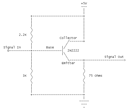
Here is the circuit diagram. It is a basic emitter follower circuit:

I built this by just soldering the resistors and the transistor together, and
did not put this on any kind of circuit board. After you have built this
little circuit, you unsolder the 1st wire from the right of the RF modulator
as you look at it from the front of the computer, and then solder that to the
Signal In of this circuit. You then connect the Signal Out line to the 1st
terminal from the right of the RF modulator, and also connect it to pin 4 of
the DIN connector. You should use shielded wire when you connect the Signal
Out line to pin 4 of the DIN connector. You can connect the ground wire to any
major ground point on the mother board. I hooked mine to the metal case of the
RF modulator.
The +5V line is also available on the RF modulator. The 2nd pin from the right
of the RF modulator is the +5V power supply for the RF modulator.
COMPOSITE LUMINANCE OUTPUT (pin 1): To add composite luminance (black and
white signal only) to the DIN connector, connect a 75 ohm resistor between the
emitter of transistor Q6 and pin 1 of the DIN connector. You should use
shielded wire to keep noise from appearing on the line.
AUDIO OUTPUT (pin 3):
To add audio output to the DIN connector, connect a wire from the 2nd terminal
from the left on the RF modulator to pin 3 on the DIN connector.
COMPOSITE CHROMINANCE (pin 5):
I have not found a simple mod to pick up the composite chrominance signal for
the DIN connector. I have not looked terribly hard, however, since it is
possible to use the composite video output as a composite chrominance signal
on many monitors. That is how my 600XL is hooked up to my separate composite
chrominance/luminance monitor, and it looks great!
GROUND (pin 2):
I just connected pin 2 of the DIN connector to the metal box that the RF
modulator lives in. However, you should be able to hook this pin up to any
major ground point on the motherboard.
I was able to mount the 5 pin DIN connector on the back of my 600XL, between
the RF modulator and cartridge slot. It is a slightly tight fit, but you can
fit it if you are careful.