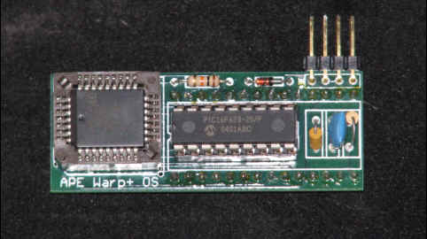
This is a picture of my 32 in 1 AtariMax replacement OS. I have this loaded into a stand alone Atari 800xl with a 256k RamDisk. You can also reprogram your 23 in 1 with the OS's you want. I am going to work on adding a little circuit board that will give me 1 page of ram located at $d7xx. Once I have added the page of ram Ultra-Speed Plus will work. I will also add the Multiplexer, Turboss, Turboss Plus OS to my 32 in 1 module.
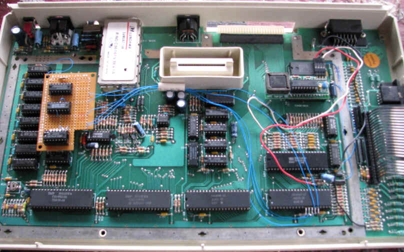
Here is a picture of my 32 in 1 installed into an Atari 800xl with 256k RamDisk. The only thing not showing is my SIO2PC I use with this computer.
Installing the 32 in 1 was an easy upgrade into the 800xl that is all socket. If you decide to install this into an Atari that does not have socket make sure that you have mastered soldering on the Atari. The Atari requires advanced soldering skills to work on the XE series of computers. Working on an Atari Mother Board requires good soldering equipment. NEVER, NEVER, Never use de-soldering braid this will cause the circuit traces to delaminate. Always use a devac tool, and use a grounding strip on your wrist. This will make sure you are grounded and less likely to pop a chip. If you have any doughty about your soldering skills have it done by a professional. Trying to do this with out the right tools and skills will make your computer into a paperweight. I think AtariMax will install their equipment for a small service charge.
 Step
#1
Step
#1
Remove the cover from the computer by releasing the four screws on the bottom
of the unit.
 Step
#2
Step
#2
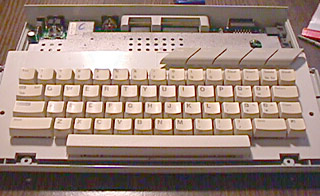
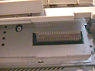
Carefully lift the keyboard to reveal the flex cable
connecting it to the main PCB.
Gently pull upwards at the base of the flex cable to part it from its socket.
Be very careful with this cable, bending it can destroy it.
 Step
#3
Step
#3
If your 130XE still has the RF shield installed, you will need to remove it
to access the PCB.
To remove the top RF shield you must straighten a number of metal tabs around
the edge of the shield using needlenose pliars.
After unbending these tabs, the top shield should lift off.
 Step
#4
Step
#4
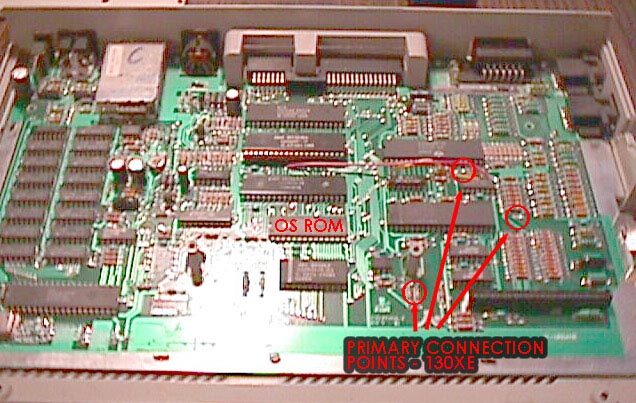
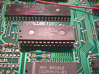
After removing the RF shield, locate the OS ROM on the
motherboard.
Its location is marked on the photograph.
If your OS ROM is soldered in, continue to step 5 to
replace it with a socket.
If the OS ROM is socketed, skip ahead to step 8.
 Step
#5
Step
#5
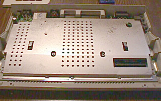
In order to desolder the OS ROM, you will need to remove
the motherboard from the case and remove the lower RF shield.
To remove the PCB and lower RF shield, remove the six
phillips screws holding the board to the case. Three are located at the front of
the PCB. The others are located at the rear near the power switch, monitor jack
and SIO port.
Mounting screw position may vary by where and when your
130XE was manufactured. Once you have all the screws removed, you can carefully
life the PCB out of the case.
The lower RF shield is held in place by the tabs you
straightened in step 3 and should come off without any extra effort if the tabs
are straight.
 Step
#6
Step
#6
Carefully desolder the OS ROM.
Be very careful when removing the ROM after desoldering.
The traces on the 130XE motherboard are VERY FRAGILE and will delaminate easily
from excess heat or force. If the ROM does not lift out easily, re-check your
desoldering work before proceeding.
In the empty place where the OS ROM was located, install
and solder in place the 28-pin DIP socket included in your installation kit.
The completed work is shown here, with a socket ready to
accept the Warp+ OS upgrade.
 Step
#7
Step
#7
Testing the socket installation.
DO NOT SKIP THIS STEP.
Take the original OS ROM you desoldered, straighten any
bent pins, and carefully insert it into the new socket.
Hook up the power and monitor connections to the Atari and
verify the system operates normally.
If the system does not operate normally then you need to
recheck your socket installation work.
The most common sources of failure at this point are torn
traces, bent socket pins or an improperly inserted OS ROM.
DO NOT PROCEED past this step until the
system functions normally.
Step #8
Carefully remove the OS ROM from its socket and place it in
the anti-static container your upgrade came in.
If you ever want to restore your computer to it factory
configuration, you will need this
 Step
#9
Step
#9
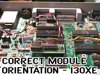
Remove the Warp+ OS upgrade board from its package and insert the board into
the OS ROM socket.
The photo on the right shows the correct orientation of the OS board in the
Atari. Do not insert the board backwards or it will be damaged. Damaged boards will
not be replaced.
DO NOT APPLY EXCESSIVE FORCE INSERTING THE BOARD.
If you encounter too much resistance inserting the board into the socket,
check the alignment of the pins in the socket and make sure it is correct.
Press straight down on portion of the board over the OS ROM socket to insert
it. Do not insert the board at an angle or one side at the time, as this will
bend or break the gold pins.
Once the board is inserted, look underneath it to verify all the gold pins
are in the socket. If any are hanging over the edges then remove the board and
re-insert into the socket correctly.
 Step
#10
Step
#10
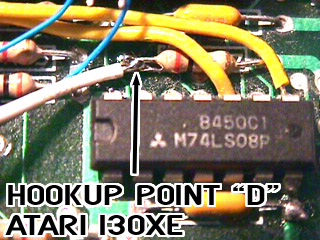
A wire set for 3 solder connections is included with your
OS upgrade.
Connection point 'D' is the left side of R87 in the 130XE.
Connect the WHITE wire to this point.
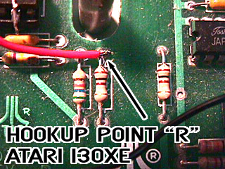 Connection
point 'R' is the top pad of R40 in the 130XE. Connect the RED
wire to this point.
Connection
point 'R' is the top pad of R40 in the 130XE. Connect the RED
wire to this point.
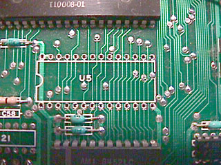
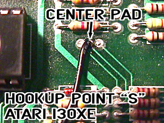 Connection
point 'S' is the center pad in a group of three, just to the right of the ANTIC
chip on the right side of the board.
Connection
point 'S' is the center pad in a group of three, just to the right of the ANTIC
chip on the right side of the board.
See the large photo above for its location. The photo to the right is a
close-up of this location
Be careful not to bridge the connection between any of these pads.
Connect the BLACK wire to this point. If your wiring kit
includes two black wires, cut one black wire off near the connector (it does not
matter which one). Only one black wire is required.
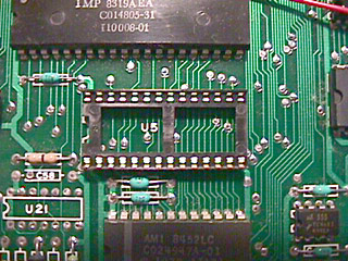
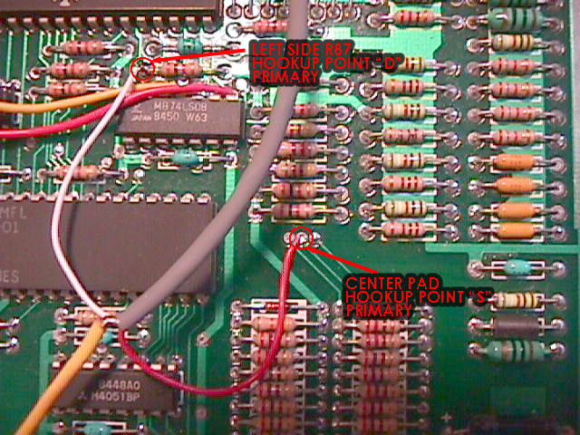 Another
photo showing points 'S' and 'D' with wires sucessfully attached.
Another
photo showing points 'S' and 'D' with wires sucessfully attached.
Disregard wire colors, they may be different in your kit.
 Step
#11
Step
#11
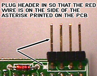
Once you have soldered the 3 required connections, you must plug them into
the header on the OS Upgrade board.
Align the header so that the RED wire is nearest the asterisk (*) printed on
the circuit board.
Attach the power and monitor connections to the Atari and turn it on.
The system should start normally (possibly with a dark-blue screen), and you
should reach BASIC or SELF-TEST.
If the system does not function normally, check all connections.
Reassemble system and re-test
On some models you made need to omit the RF shield during re-assembly or make
a hole in it to accomodate the module.
Hold SELECT down on the keyboard while powering up the Atari to reach the OS
Selection Menu.
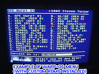 The
descriptions you entered when building your OS will appear on screen. Simply
select a new OS using the keyboard and the system will reboot using that OS.
The
descriptions you entered when building your OS will appear on screen. Simply
select a new OS using the keyboard and the system will reboot using that OS.
Every time you power on the Atari it will use the OS you selected. To change
the OS again, just hold down SELECT while turning on the computer.
You may also hold SELECT+OPTION down on the keyboard while powering up to
reach the APE Remote Control software.